

Authors: Charisios Loukas, Evangelos Mageiropoulos and Nikos Chrysos, FORTH
Don’t miss the demo at the end of this article!
Low-latency inter-node communication is important in HPC clusters. Following the conclusion of the ExaNeSt project, which studied the adoption of low-cost, power-efficient Arm processor clusters for Exascale-class systems, as part of the RED-SEA project, we swapped the Arm processors for RISC-V. In this work, we tightly coupled a lean, low-latency network interface with a modified Ariane RISC-V soft core.
Hardware Testbed
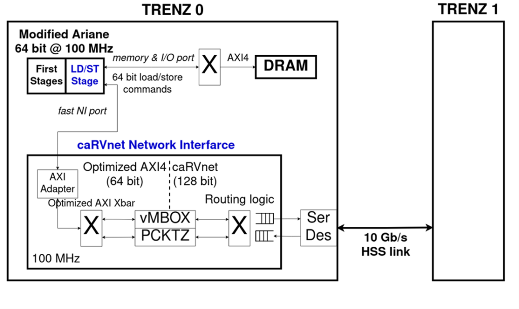
Our system, shown in Figure 1, consists of 2 TE0808 Trenz boards, each equipped with a XCZU9 Xilinx MPSoC, with a custom design based on the Ariane CVA6 64-bit RISC-V core programmed on its FPGA and running at 100 MHz. The two boards are connected in a Ring topology over the caRVnet network, using a pair of HSS 10Gbps cables.
The caRVnet Network
caRVnet is a custom cell-based network developed in FORTH, inside the RED-SEA project. It allows distributed memory access across boards, using low-latency user-level RDMA and packetizer-mailbox primitives. The caRVnet datapath of the tested design has a word width of 128 bits and runs at 100 MHz, for 10 Gb/s links, but there is a newer design under testing with a 512-bit datapath running at 200 MHz, to support 100 Gb/s line rate. The caRVnet packets consist of 16 words of payload, transferring a maximum of 256 bytes on the tested design, plus 256 bits of control data.
The network packets are formed by the caRVnet Network Interface (NI), which is connected to the LD/ST stage of the Ariane core as can be seen in Figure 1. Data for the formation of those packets is passed from the Ariane core to the caRVnet NI in the form of store instructions which target a dedicated address range.
The use of the standard Ariane I/O port to connect to the NI caused the packet formation to slow down significantly. The default I/O port could issue 1 store per 7 cycles. Thus, we modified the LD/ST stage of the Ariane, to allow back-to-back stores to the NI, as well as load commands every other clock cycle. Essentially, we created a new port in the LD/ST stage for NI addresses. To receive load/store commands, the caRVnet NI uses a custom AXI adapter that converts load/store commands to AXI commands, and optimized AXI4 interconnect. These modifications tightly couple the Ariane core with our network interface.
As shown in Figure 1, the main hardware primitives of the NI examined in this work are a Packetizer and a Mailbox. In our tests, we evaluate user-level communication, in which processes issue network packets via the Packetizer, and receive them by polling the Mailbox. Network packets are routed in the ring network via the caRVnet interconnect with 1 cycle cut-through latency. We use custom 10 Gb/s transceivers with one way latency of 100ns.
caRVnet Virtualized Packetizer
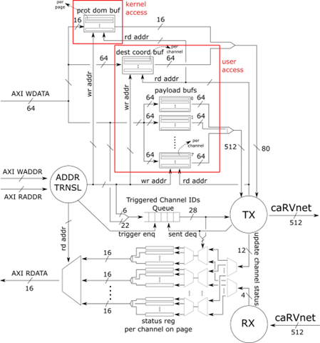
The caRVnet Packetizer, shown in Figure 2, is a virtualized caRVnet network peripheral responsible for small low-latency messages that fit in a packet. A process can issue a packet from user-space by writing the payload via store instructions into an allocated page. Multiple processes can store data in Packetizer’s memory, via separate pages, and each page is further partitioned in channels. The Packetizer has one slave AXI-4 port connected to the LD/ST stage as shown in Figure 1.
The address space of the Packetizer that is exposed to the processors is divided between kernel accessible space and user-process accessible space. The user accessible space is divided into 64 virtual/HW-isolated pages (4K each) and each page includes 4 channels accessible by using specific in-page offsets. Once the data to be transferred has been written to the channel of the allocated page, the packet formation and transmission is triggered by writing a trigger word. The trigger word consists of the destination address (LS 42 bits), the destination coordinates (22 bits), the size in bytes (14 bits). The Packetizer waits end-to-end acknowledgements and implements hardware timers (8 bits). timeout value multiplied by 20 microseconds (8 bits) and the auto-chaining enable (1 bit).
Figure 2 depicts the hardware architecture of Packetizer, which is optimized for ultra-low packet latency, accepting back-to-back stores from the processor and issuing packets with just one cycle latency after all words have been received. When a channel is triggered, its ID is enqueued to a FIFO that leads to the internal transmission-controller. The transmission-controller consumes the info on the head of FIFO and gathers the data from the buffers, to which the user has already stored the contents of the desired packet and generates the caRVnet packet in order to send it to the network.
We also implement an auto-chaining function that enables the ordering of packets within a page. The user triggers a channel with the auto-chaining bit enabled in the trigger word and the controller will check first if the previous channel in the same page has already received an acknowledgment packet.
caRVnet Virtualized Mailbox
The caRVnet Virtualized Mailbox is an endpoint component of the caRVnet NI, suitable for many-to-one communication. It receives caRVnet packets through its caRVnet interface and stores their payload so that it can be accessed by user-level processes through an AXI-Read interface. As shown in Figure 3, the Mailbox implements multiple virtual mailboxes into separate buffers.
When a packet arrives, the Mailbox checks the capacity of the targeted buffer. If there is not enough space, the packet is dropped. When all the payload words of the packet have been enqueued in the targeted mailbox, the hardware issues a response packet to the sender Packetizer. User-level processes can read the size and the (head) data of each virtual mailbox via load commands, as can be seen in Figure 1.

System Software
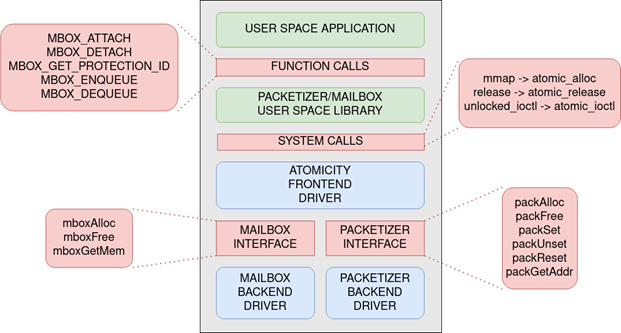
The software required for the user to be able to send and receive data using the Packetizer/Mailbox hardware is shown in Figure 4 and consists of the following layers:
- The Packetizer and Mailbox back-end drivers, which handle basic interactions with the hardware, and the Atomicity front-end driver which exposes a single interface for both devices to the user level,
- The user-space library, which implements a set of functions that allow the user to communicate with the kernel space drivers in order to send and receive messages using the Packetizer/Mailbox hardware,
- The user-level runtime, that runs a specified number of ping-pong iterations between user spaces in adjacent nodes, in order to gather caRVnet communication latency results.
Packetizer/Mailbox drivers
To provide user-level access to our hardware, we first need the OS to identify the base address of each hardware module. The kernel module that implements this functionality comprises two backend drivers that have direct access to the kernel-accessible memory of each device, as well as a frontend driver that controls access to both backend drivers and provides user-level access to them via a set of system calls.
Both backend drivers read and store the base address of their corresponding device from the device tree. They are tasked with monitoring the virtualized hardware availability, configuring each allocated instance upon allocation and providing the information necessary for accessing the allocated hardware in kernel space.
The Atomicity frontend driver exposes a set of system calls to user-space, through which the user can gain access to the user-accessible memory page on an allocated Packetizer/Mailbox pair. The driver achieves this by using the functions the backend drivers expose in order to allocate and configure one instance of virtualized hardware. The driver then maps the base address of this instance to a virtual address which is then returned to the user via the system call.
User-space library
The user-space library is a set of hardware-aware user-level functions that call upon the Atomicity driver system calls to obtain a pair of Packetizer/Mailbox devices and use them to send and receive packets between remote nodes. With this library the user no longer needs to know how the hardware works and needs only follow the library documentation. The user interface of the library is made up of the following functions:
- MBOX_ATTACH: allocates a Packetizer/Mailbox pair by invoking the mmap system call
- MBOX_DETACH: deallocates the allocated Packetizer/Mailbox pair (invokes the release system call)
- MBOX_GET_PROTECTION_ID: returns the protection ID of the process to which the Packetizer/Mailbox pair has been allocated to (invokes the unlocked_ioctl system call)
- MBOX_ENQUEUE: Writes a payload to the Packetizer and triggers the packet formation and transmission
- MBOX_DEQUEUE: Reads the payload of an incoming packet from the Mailbox
The library also includes a few additional functions that are either called internally and are not necessary to the user, or are simply variations of the enqueue/dequeue functions that allow, for example, non-blocking mailbox reading.
User-space runtime
To measure the user-space latency of our system, we implemented a user-space program that calls on the aforementioned user-space library functions. Latency between two adjacent remote nodes is measured in one of the two nodes by a user space program which implements a repeating ping-pong test. Each node sends a 32-byte packet to a remote Mailbox and starts polling its own Mailbox for a response. Once the opposite node receives the packet by polling its own Mailbox, it sends back another 32-byte response packet. The ping-pong iteration concludes with the first node reading the response packet from its Mailbox. Latency is measured per iteration, in one of the two nodes, using the RISC-V performance counters by means of the rdcycle assembly instruction.
Results
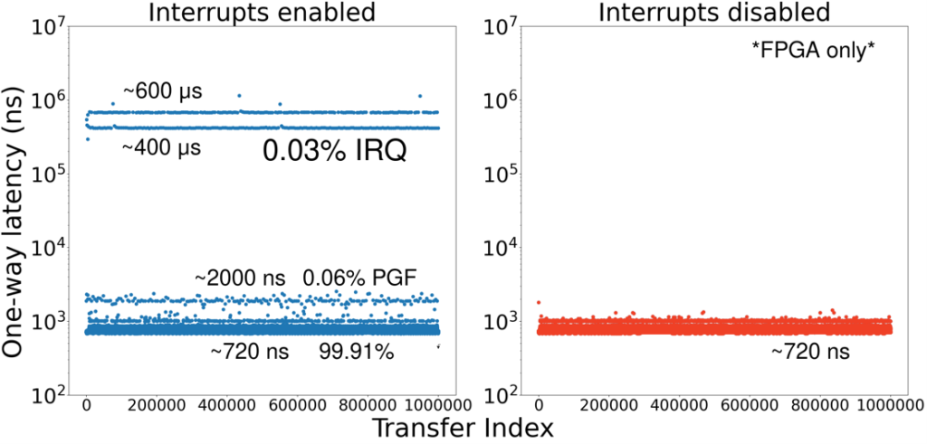
After optimizing both the runtime and the library, we achieved a one-way user-level latency of 930ns between two adjacent nodes in the ring network. However, observations of packet transfers in real time using the Vivado Logic Analyzer consistently showed a one-way latency of 720ns. This discrepancy implied the existence of outliers, which we subsequently measured by taking per iteration latency samples.
As can be seen in the first graph of Figure 5, the latency measurements vary significantly, between 720ns and 600μs. We notice a concentration of values in 4 main plateaus. The overwhelming majority of the measurements are concentrated at 720ns. 0.03% is concentrated at 400 and 600 μs, which, based on the duration and the consistency of the overhead, can be attributed to context switches, caused by timer interrupts. The remaining 0.06% of values only reach up to 2000ns and are twice in number to the interrupt-related outliers. We assume they represent page walks, occurring at the start and the end of each context switch.
To prove these conjectures, we developed a hardware mechanism, which allows us to disable timer interrupts during measurements. This can be done from software, using inline assembly, without adding any unwanted overhead. The results can be seen in the second graph of Figure 5, where latency does not exceed 1000ns. The average one-way latency is 725ns, with the majority of measurements at 720ns.
Measurement breakdown
Figure 6 describes the sequence of events we see on the Vivado Logic Analyzer snapshot of the requesting node (indexed 0) and estimates the timing of these events on the answering node (indexed 1). For node 0 we have the following series of events:
- 0 CC: The Packetizer AWVALID signal is raised, indicating the Packetizer configuration registers are being written by the Node 0 runtime (32-byte payload requires 4 64-bit writes plus another 2 for trigger words).
- 7 CC: The header valid signal on the Packetizer outgoing caRVnet link is raised, indicating that the Node 0 packet is traversing the network.
- 22 CC: After sending its packet, Node 0 starts polling its Mailbox status (RVALID signal rises).
- 47 CC: The header valid signal on the Packetizer incoming caRVnet link is raised, indicating that the acknowledgement for the Node 0 packet has arrived at Node 0.
- 99 CC: The header valid signal on the Mailbox is raised, indicating that the Node 1 packet header has arrived at Node 0. Correspondingly, payload valid signal will be active at CCs 100 and 101 and footer valid at CC 102. After that, the next Mailbox poll (which may come 1-5 CC after) will return an active status.
- 107 CC: Mailbox polling returns an active status, indicating to software on Node 0 that a packet has arrived, thus prompting it to read the packet payload.
- 129 CC: The Node 1 packet has been read at Node 0.
- 144 CC: A new Node 1 packet begins being written into the Packetizer (start of next iteration).
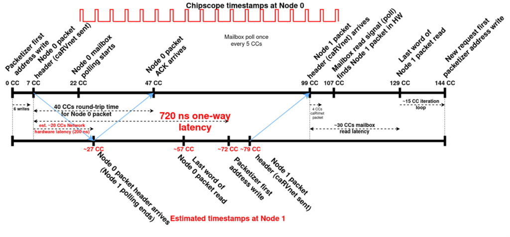
Summarizing, if we remove the network latency, the one-way user-level latency is just 52 CCs. In our FPGA running the RISC-V with the closely-coupled network interface at 100MHz, this translates into 520 ns latency at runtime and NI operations, but in an ASIC implementation running at 1 GHz, the user-level one-way latency, excluding the network link, could be as low as 52 ns.
Demo
This demo show cases the sub-μsec one-way latency of packets traveling between two Trenz nodes, connected in a Ring topology, from the Packetizer of one node to the Mailbox of the other and vice-versa.